FreeCADのAssembly3ワークベンチを使ってアンチバランスタブのリンク機構をモデリングする
FreeCADのバージョンは0.19
はじめに
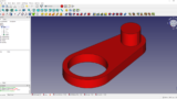
最終的にはこんなものを作る
Assembly3でアンチバランスタブ #FreeCAD pic.twitter.com/0cvrhhIlt6
— いーそー (@mtk_birdman) May 14, 2022
↓前回の記事では,リンク機構の寸法の設計と各パーツのモデリングを行った
この記事では,作成したパーツを使ってリンク機構のモデリングを行う
↓FreeCADの公式ドキュメントはこちら

それではいってみよう
Assembly3とは
FreeCADではデフォルトでアセンブリの機能は搭載されておらず,外部のアドオンを使ってアセンブリを行う必要がある
FreeCADでアセンブリを行えるアドオンには主にAssembly3とAssembly4の2つがある
今回は「筆者が以前使用していたFusion360のアセンブリ機能と同じようなことができる」という理由でAssembly3を使うことにした

↓Assembly3の使い方で参考にしたのはこちら
インストール
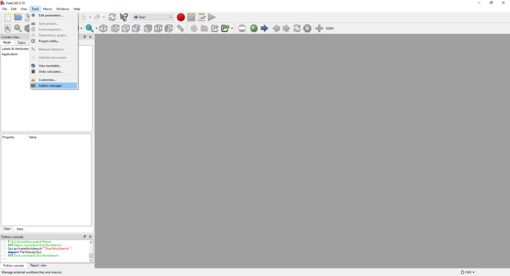
「Tool>Addon manager」をクリックする
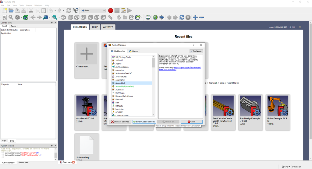
「Addon Manager」が開くので,Assembly3を選んで「Install/update selected」をクリックする
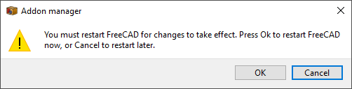
インストールが終わったらAddon Manegerを閉じて,指示に従いFreeCADを再起動する
以上でAssembly3のインストールは完了である
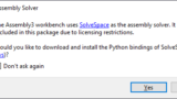
↓インストールしたときに出たちょっとしたエラー
参考
≫FreeCAD アドオン・マネージャーで追加機能をインストールする - XSim
リンク機構のモデリング
リンク機構のモデリングはざっくり以下の手順で行う
- アセンブリ用のドキュメントの中に各パーツのオブジェクトリンクを作成する
- 1つのパーツを固定する
- パーツごとにAxial拘束とPointInPlane拘束をかける
- リンク機構を動かして遊ぶ
それでは具体的にAssembly3を使ったリンク機構のモデリングを説明していく
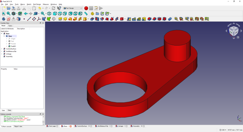
まずは前回の記事で作成した4つのパーツのドキュメント(AntiBalanceTab,Base,ControlSurface,Linkage)を開き,アセンブリ用の新しいドキュメント(Assembly)を作成する
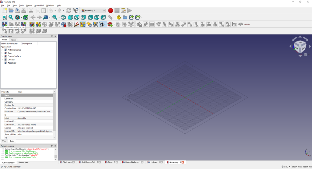
Assemblyのドキュメントをアクティブにして,左上のアイコンから新しいAssemblyオブジェクトを作成する
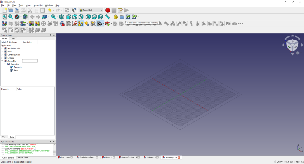
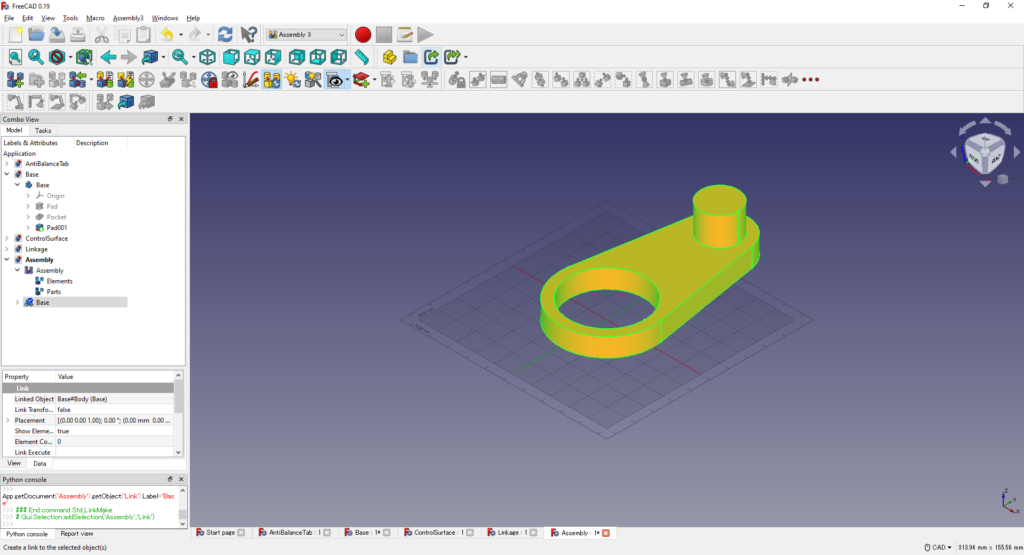
Baseのドキュメントの中のBodyオブジェクトを選択し,真ん中上のアイコンからオブジェクトリンクを作成する
≫FreeCAD 複数のファイルを組み合わせて1つのファイルにまとめる - XSim
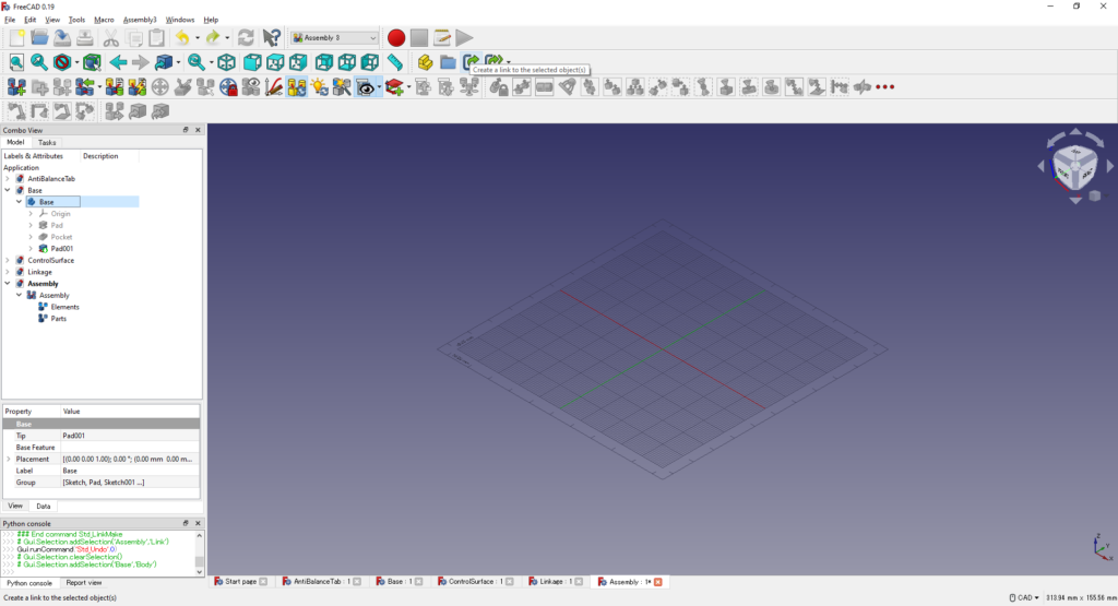
Assemblyのドキュメントの中にBaseのBodyオブジェクトが追加される
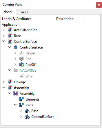
同様の手順でControlSurfaceのオブジェクトリンクを作成する
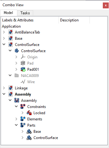
Tree View上でBaseとControlSurfaceを選択し,ドラッグして「Assembly>Parts」の中に入れる
Baseオブジェクトの上面を選択し,真ん中上のアイコンからLock拘束をかける
Tree Viewに「Constraints>Locked」が追加される
アセンブリをやりやすくするために,重なり合っている2つのパーツの位置をずらす
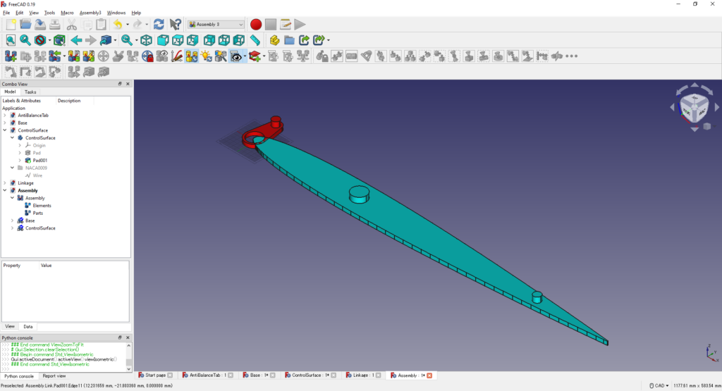
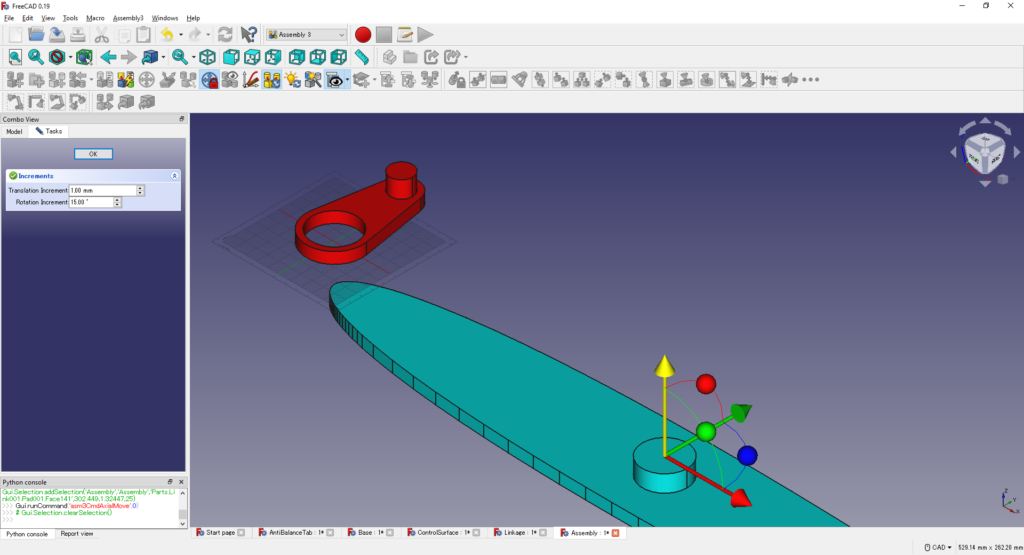
ControlSurfaceの上面を選択し,左上のアイコンからAxialMoveをクリックする
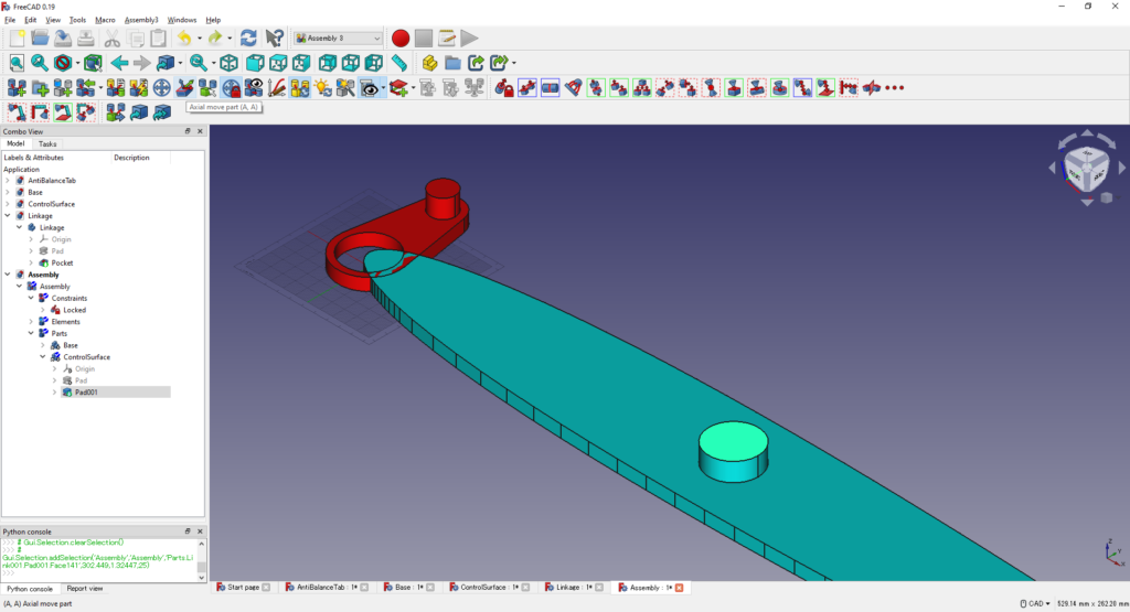
平行移動と回転ができそうなアイコンが表示されるので,Z方向の矢印をドラッグして下方向に適当に動かす
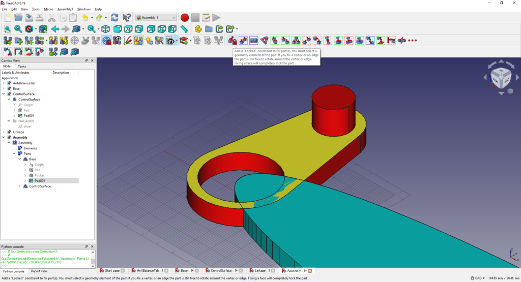
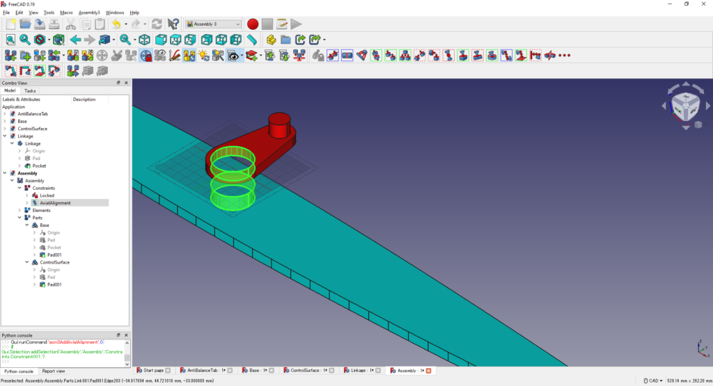
BaseのPocketの側面と舵面の回転軸の側面を選択し,Axial拘束を適用する
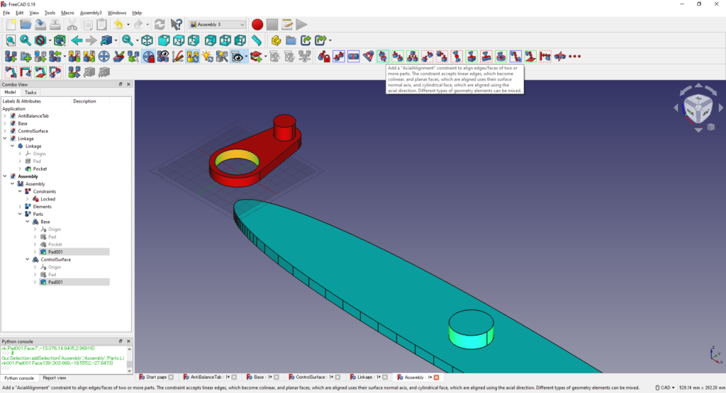
先ほど固定したBaseオブジェクトは動かず,ControlSurfaceオブジェクトが動いてAxial拘束される
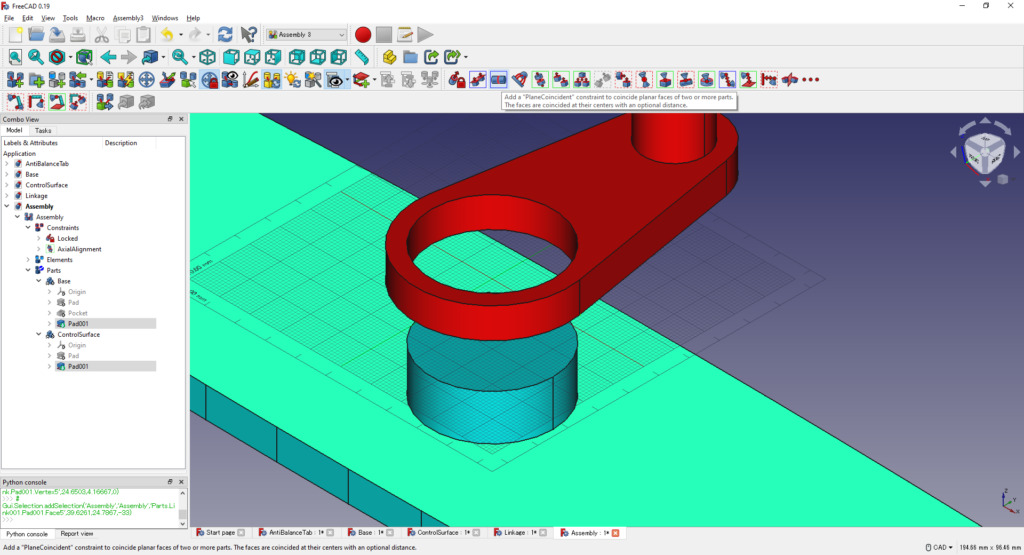
2つのオブジェクトが離れているので,接するような拘束を追加する
Baseオブジェクトの側面下端の点(分かりにくい)を選択する
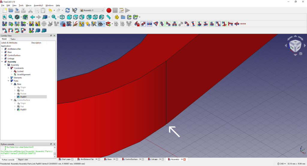
Ctrlキーを押しながらControlSurfaceの上面を選択する
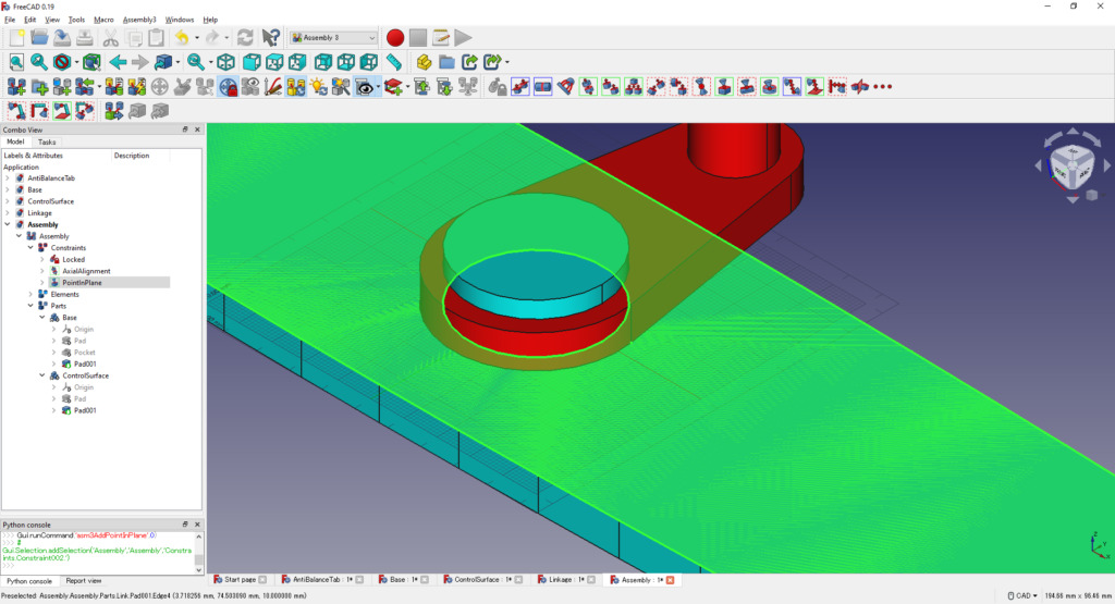
選択した点と面に対してPointInPlane拘束を適用する
同様の手順でAssemblyドキュメントの中にAntiBalanceTabのオブジェクトリンクを作成し,Z軸方向に適当にずらす
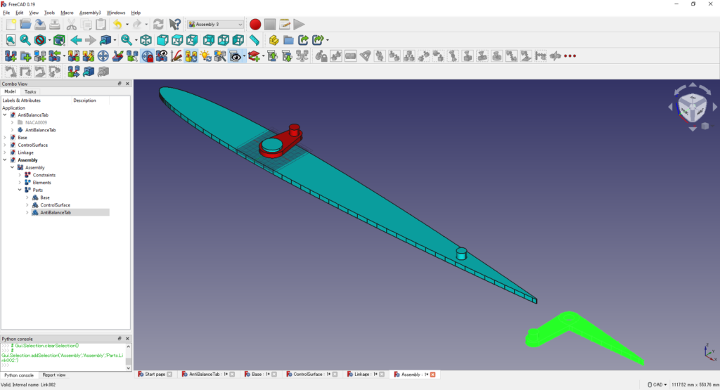
ControlSurfaceの後縁側のPadの側面とAntiBalanceTabのPocketの側面を選択してAxial拘束を適用する
AntiBalanceTabの下面にある点とControlSurface上面を選択してPointInPlane拘束を適用する
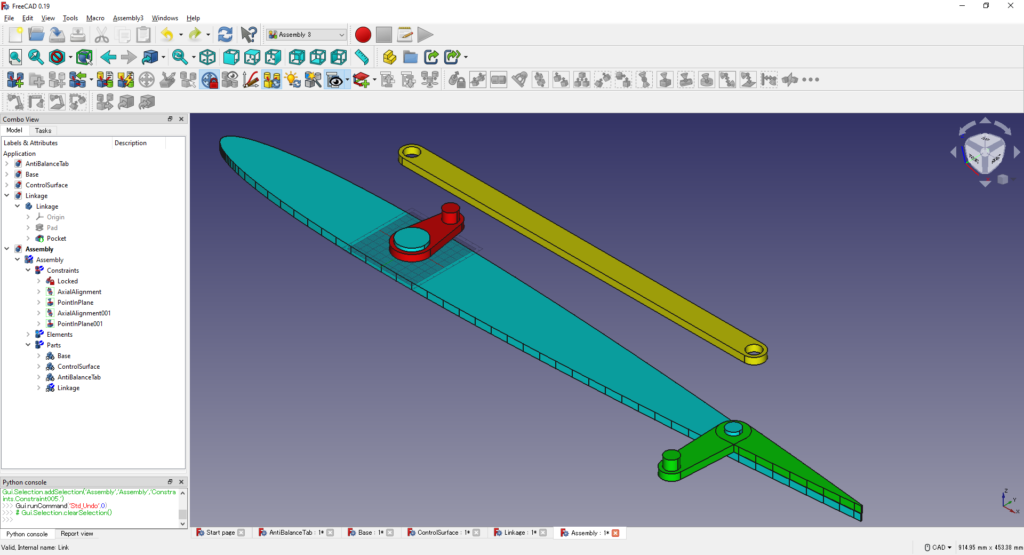
ここまででこんな感じ
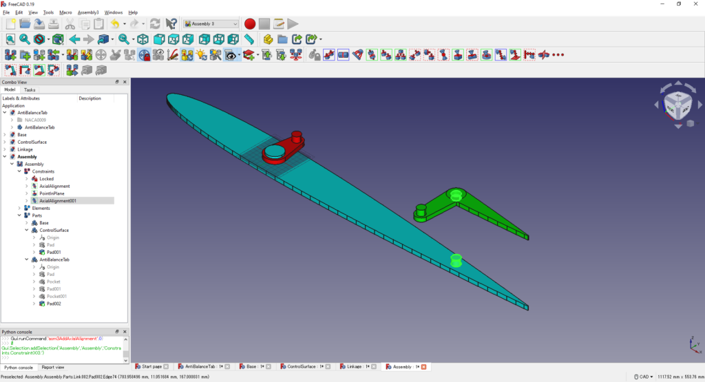
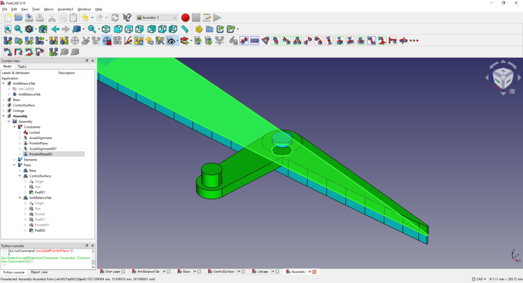
Assembkyのドキュメント内にLinkageのオブジェクトリンクを作成し,Z軸方向にずらす
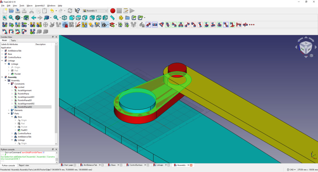
Baseの上面のPadの側面とLinkageの前縁側のPocketの側面に対してAxial拘束,Linkageの下面の点とBaseの上面に対してPointInPlane拘束を適用する
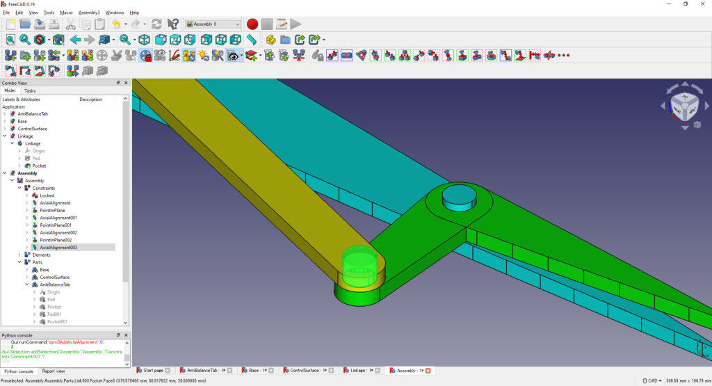
最後にLinkageの後縁側のPocketの側面とAntiBalanceTabの上面のPadの側面に対してAxial拘束を適用する
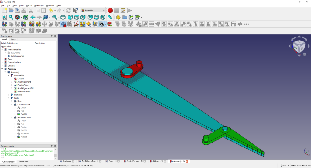
これでアンチバランスタブのリンク機構のモデリングが完成した
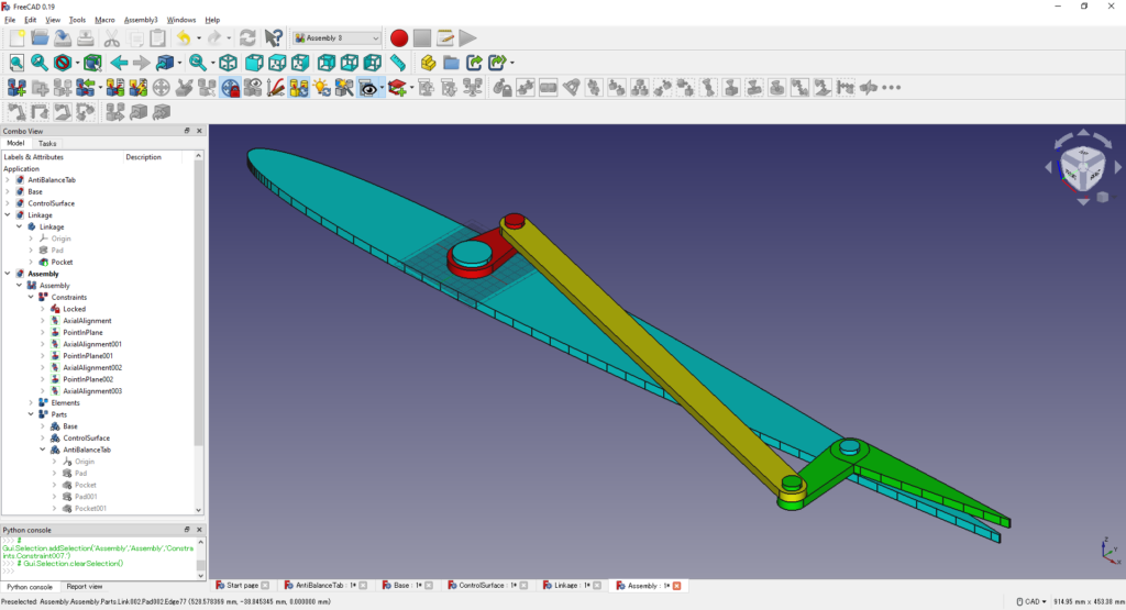
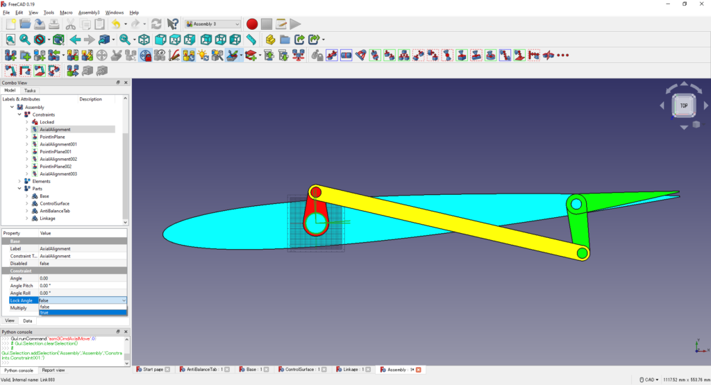
舵角が0度からずれてしまっているので,Tree Viewから「Assembly>Constraints>AxialAlignment」を選択し,「Property>Data>Constraint>Lock Angle」を「True」にする
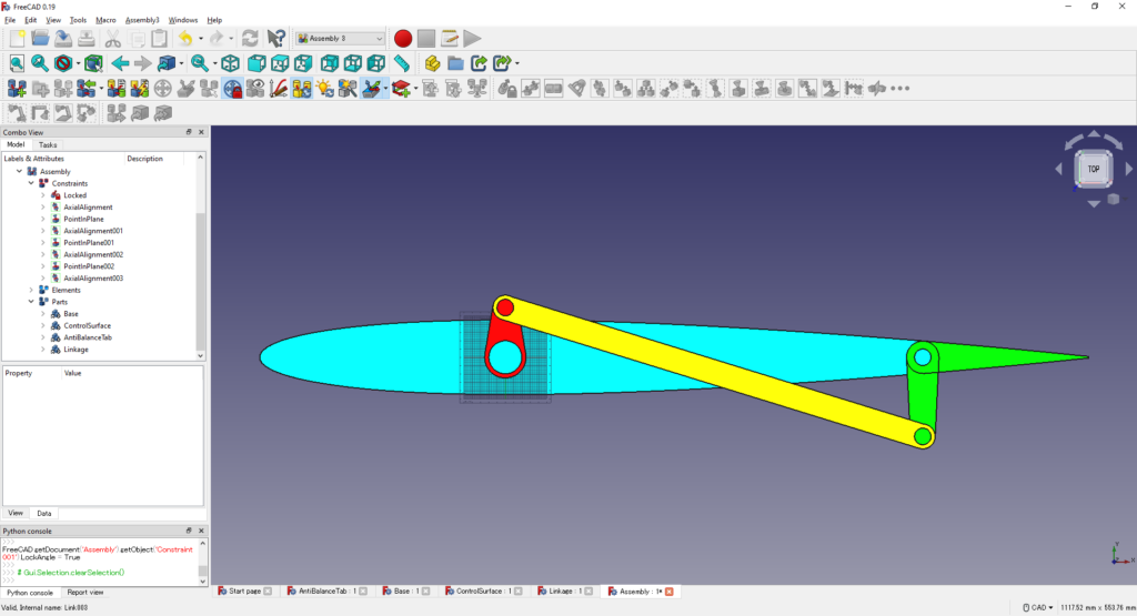
舵角が0度に戻り,すっきりする
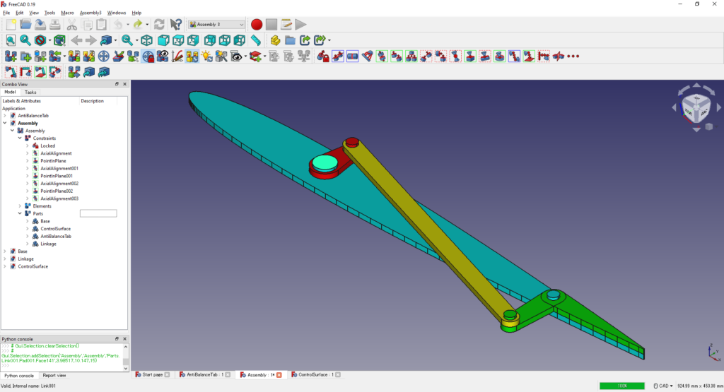
リンク機構を動かす
モデリングしたリンク機構をぐりぐり動かして遊んでみる
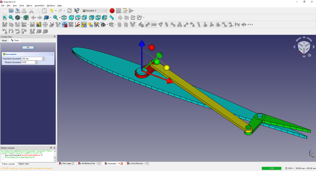
ControlSurfaceの回転軸の上面を選択してAxialMoveをクリックする
Z軸回りに回転できそうな丸いアイコンをドラッグすると,舵面を回すことができる
Windows10に標準装備されている画面録画の機能を使えば,最初に示したtweetのような楽しい映像をとることもできる

↓楽しい映像
Assembly3でアンチバランスタブ #FreeCAD pic.twitter.com/0cvrhhIlt6
— いーそー (@mtk_birdman) May 14, 2022
おわりに
FreeCADのAssembly3ワークベンチを使ってアンチバランスタブのリンク機構を設計した
FreeCADは誰でも無料で使えるオープンソースの3DCADソフトだが,筆者が以前使っていたFusion360と同じようにリンク機構のモデリングをすることができた
「タダより安い物はない」という言葉の通り,オープンソースのソフトウェアのデメリットの1つに「ドキュメントが不親切で学習コストが高い」がある
ただ,OpenFOAMの例からもわかるように,便利なソフトであればいずれ有志によってドキュメントは充実してくると予想される
このブログもその一端を担う存在になれることを願っている
↓関連記事

↓おすすめ記事
コメント